Q1(a): Define Universal Gates
Universal Gates are logic gates that can be used to implement any Boolean function without needing any other gate type. The two main universal gates are NAND and NOR.
NOR: Y = (A + B)'
Q1(b): Implement Basic Gates using NOR

NOT Gate using NOR:
Connect both inputs of a NOR gate together.

OR Gate using NOR:
Invert the output of a NOR gate to get an OR function.

AND Gate using NOR:
Invert the inputs before feeding them into a NOR gate.

Q2(a): Simplify a 3-bit expression using K-Map
A Karnaugh Map (K-Map) is a graphical method to simplify Boolean algebra expressions. It helps minimize the number of logic gates required.
Example: Simplify F(A,B,C) = Σm(0,2,4,6)

Simplified Expression: F = C'
Q2(b): Simplify a 2-bit expression using K-Map
Example: Simplify F(A,B) = Σm(1,2)

Simplified Expression: F = A' + B'
Q3(a): Half Adder
A Half Adder adds two single bits and produces a Sum and a Carry output. It does not account for a carry-in from a previous stage.

Sum (S) = A ⊕ B
Carry (C) = A · B
Q3(b): Full Adder using Half Adders
A Full Adder adds three bits (A, B, and a Carry-In) and produces a Sum and a Carry-Out. It is the fundamental building block for multi-bit adders.
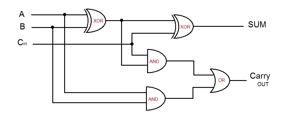
Sum (S) = A ⊕ B ⊕ Cin
Carry (Cout) = A·B + B·Cin + A·Cin
Q3(b.1): Full Adder using Decoder
A Full Adder adds three bits (A, B, and a Carry-In) and produces a Sum and a Carry-Out. It is the fundamental building block for multi-bit adders.

Q3(c): Subtractor
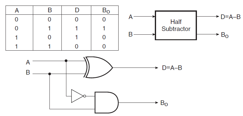
A Subtractor is a digital circuit that performs subtraction of binary numbers. There are two types: Half Subtractor (subtracts two bits) and Full Subtractor (subtracts three bits including a borrow).
Half Subtractor
Difference (D) = A ⊕ B
Borrow (Bout) = A' · B
Q4(a): Encoder Definition
An Encoder is a combinational circuit that converts information from 2^n input lines into an n-bit binary code. It has more inputs than outputs and produces a binary code corresponding to the active input line.

Q4(b): Decoder Definition
A Decoder is a combinational circuit that converts binary information from n input lines to a maximum of 2^n unique output lines. It has more outputs than inputs and activates a specific output line based on the binary input.

Q4(c): Encoder vs. Decoder
| Feature | Encoder | Decoder |
|---|---|---|
| Function | Converts 2^n inputs into an n-bit binary code. | Converts an n-bit binary code into 2^n unique outputs. |
| Operation | Compresses data (many-to-few). | Expands data (few-to-many). |
| Example | 8-to-3 Encoder (8 inputs, 3 outputs). | 3-to-8 Decoder (3 inputs, 8 outputs). |
| Use Case | Keyboard encoding, converting keypad presses to a binary value. | Memory address decoding, selecting one of many memory locations. |
Q4(d): Applications of Encoder and Decoder
Applications of Encoder:
- Keyboard encoding in computers
- Data compression systems
- Position encoding in robotics
- Analog-to-digital conversion
Applications of Decoder:
- Memory address decoding in computer systems
- Display drivers (e.g., 7-segment display)
- Instruction decoding in CPUs
- Data routing in communication systems
Q5(a): Multiplexer (MUX)
A Multiplexer (MUX), or data selector, is a circuit that selects one of several input signals and forwards it to a single output line. The selection is controlled by a set of select lines.

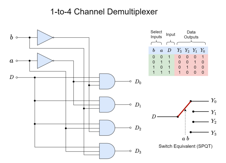
Q5(b): Demultiplexer (DEMUX)
A Demultiplexer (DEMUX) performs the reverse operation of a MUX. It takes a single data input and routes it to one of many possible outputs, based on select lines.
Q5(c): Applications of MUX & DEMUX
Applications of MUX & DEMUX:
- Communication systems
- Data routing
- Control systems
- Switching circuits
Exam Tip:
Remember that MUX and DEMUX are complementary devices. MUX selects one input from many, while DEMUX routes one input to one of many outputs. Both are controlled by select lines.